
Latent only cooling is a method of utilizing the cooling energy of air leaving an existing or new construction fan coil air handler, to simultaneously pre-cool the air entering the air handler and reheat the air leaving the cooling coil. Installations and field tests have shown this can take an average fan coil either dx or chilled water and render the unit up to over 95% latent with very little temperature change.
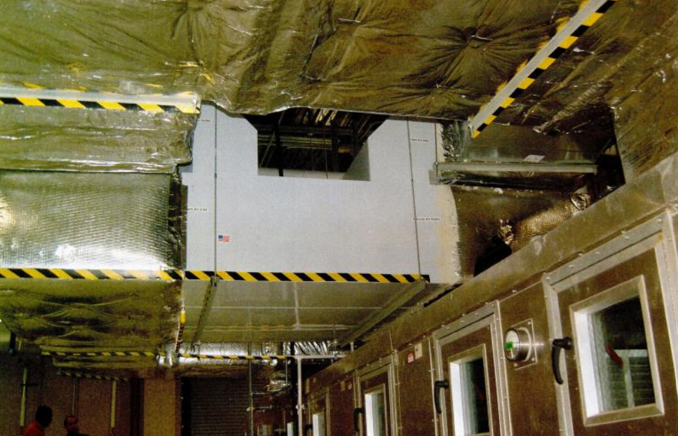
In the above photo, a 6,000-cfm latent only unit that not only saves energy but allows better humidity and moisture control in an industrial plant. located in a tropical jungle climate. When the fan speed is adjusted we have found the leaving air temperature to approach within less than one degree Fahrenheit the entering temperature. Part of this is due to moisture or latent heat of condensation that has more effect on the air that has left the cooling coil to reheat this air to near the starting temperature or room temperature. This effectively allows very precise control of the moisture in the air without dropping the temperature.
Clients have used this for both outside air or for air recirculated from the space. We find recycling the air from the space allows the most efficient and precise control. A separate system can be used to bring in outside air and exhaust air from the space. A combination of recycled air and mixing this with pre-tempered fresh outdoor air can also be used. BPE energy recovery modules can be automatically, based on engineering design, track the interior space temperature, this is the engineering nature of a true direct counter flow heat exchanger.
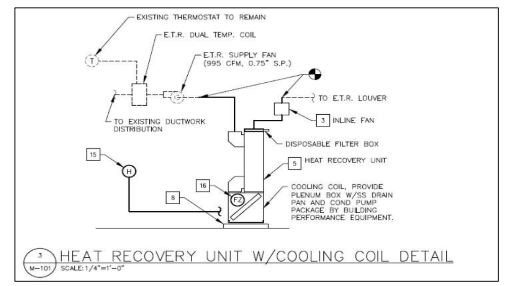
The diagram above is a latent only device that uses a BPE unit and a chilled water coil as a run around loop to drastically reduce the required re-heating and cooling capacity. When in steady operation, return air from the space will be pre-cooled through the exhaust plenum of the heat exchanger by air leaving the cooling coil (supply air). By absorbing the heat of the return air, the supply air not only assists in pre- tempering the return air before the cooling coil, but in addition, reheats itself. It has been found through testing that this can reduce 80% of the sensible load and some of the latent load as well as greatly reduce the cooling tonnage needed to dehumidify air. Latent only cooling systems have actually been shown to supply air within half of a degree of room temperature, effectively creating what we call a latent only device. This is useful in dealing with very moist locations or in climates where the humidity load can be excessive for a long period of time. Typically, the unit is run off a humidistat and only operates when the relative humidity goes over a certain set- point. This can be done with any of the BPE Units and is relatively straightforward. The process can be summarized by the following steps:
1) The air comes in from the space and is pre-conditioned and cooled before it sees the coil
2) Pre-cooled air enters the coil and is supplied back to the heat exchanger around 50 ̊F
3) Supply air is reheated to 70-75 ̊F by the BPE ERM
4) The reheated air is then returned to the space at nearly the same dry-bulb conditions, but much dryer. This is a huge step forward in handling relative humidity issues when there is no call for cooling.
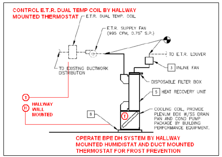
Figure 2, above, illustrates a detail of a run around latent only system with a direct expansion coil (DX), rather than a chilled water system for cooling. To solve this issue of coil freeze-up, BPE recommends installing a temperature loop which controls the operation of the refrigerant. When supply air falls below a certain temperature, refrigerant supply will terminate but airflow will continue. This process allows return air to warm up the coil thereby preventing any frost. This is engineered to provide latent only cooling – reduce relative humidity of air within a space without effecting temperature.
Tips:
No. #3 – Inline Fan is before the BPE Energy Recovery Module (ERM), pushing air into the ERM.
No. #5 – Heat Recovery Unit or ERM, is mounted vertically so the humid air condenses moisture and drips down into the air handler.
No. #8 – Drip pan – In this configuration, there is a large volume of water generated. The Air Handler and drain pan need to be properly drained.
Figure 2 – A detail for the control modules of the latent only system to prevent frost.
T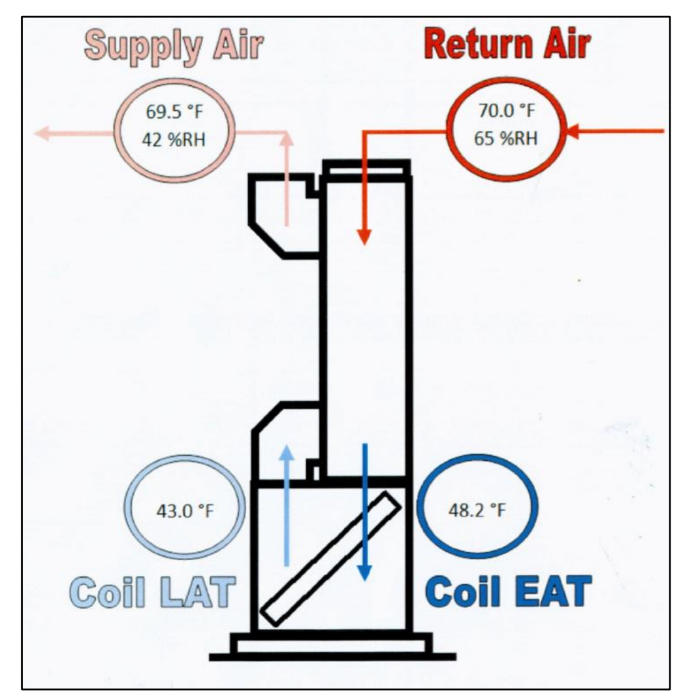 he temperatures depicted left are not theoretical but were compiled through field testing. In this example the outdoor air is coming in at 70°F, so this is the worst case scenario for a traditional heating and air-conditioning system in which the air is very humid, but no actual cooling is needed.
That is specifically what a latent only system is engineered to solve by figuring out how to wring out the moisture without adding expensive re-heat. For most buildings the re-heat would involve electric resistive heating that is actually more expensive than the cooling needed to reduce the temperature for this loop. An interesting side note is that with a direct counter-flow heat exchanger, the pre-cooled air actually wants to track the temperature that you are coming off of.
An automatic feature of this type of equipment is that it does not want to change the temperature of the air, but rather it uses the air that has been cooled to pre-cool the air coming in. Then the air that is coming into this device is ultimately the temperature that the air wants to seek after it has been pre-heated with the air that has been pre-cooled before it goes to the cooling coil. The return air comes in relatively humid at room temperature. There is no need to cool the air, it is simply wringing out the moisture. The air that had already been cooled by the coil, which in this example is now down in the low 40°F, is used to pre-cool the 70°F air to the point where it is already wringing out moisture and the temperature of this air is typically in the low 50s°F and upper 40s°F and in this example it is 48.2°F. At that temperature there is very little sensible cooling that needs to be done. 43°F is the temperature of the air leaving the coiling and now the wet bulb is below 43°F, so it is relatively dry air. As this approaches the 70°C direct counter-flow air coming down into the core it will reheat the 43°F air.
In this test case we found that the resulting temperature actually approached the return air degrees within half a degree. This eliminates the comfort problems with introducing 43°F air to a room. It also helps the dry the air out and reduces the relative humidity by increasing the temperature of the air.
In this particular application the primary comfort cooling for the space would control the temperature and this unit would be strictly driven off a humidity stat that would come on when the relative humidity went above a pre-set point, typically at 50% to 55% relative humidity.
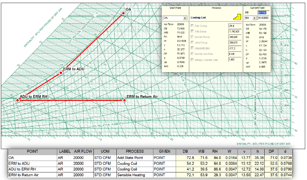
The Diagram above is called a Psychrometric Chart, which plots the characteristics of water vapor and air mixture. The red lines illustrate the behavior of the air when interacting with the BPE Latent Cooling Loop in a humid application. In this example a 20,000 cfm air flow is able to reduce cooling load by 1,192,821 btu/hr or 99.4017 tons of chilled water per hour. This allows older air handlers and equipment that is not functioning properly to work in very humid and challenging situations that traditional equipment would not be able to dehumidify without over cooling or using typically very expensive reheat. In this example the reheat is a free byproduct of pre-cooling to return air before being fully dehumidified by the cooling coil.
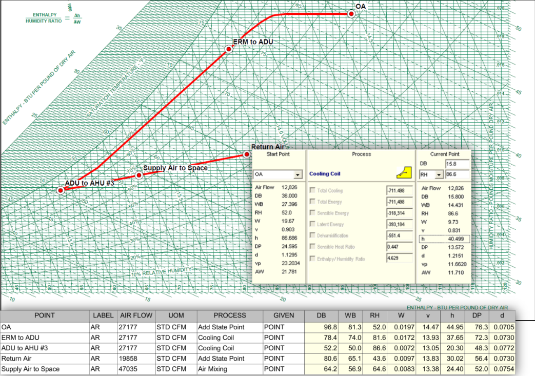
Now take a look at the results from a project in Malaysia (above). We were asked to engineer a 100% outdoor air flow of 27,177 cfm at 96.8 F and a wet bulb of 81.3 F qb, with 137.9 grains of water. This was difficult for the existing air handlers to dehumidify. With the use of BPE energy recovery modules, the 137.9 grains of moisture in the outdoor air was reduced to 58.1 grains of water per pound of air, in a single pass.